|
|
| Line 129: |
Line 129: |
| |} | | |} |
|
| |
|
| == Configuring Marlin == | | == Configuring Firmware == |
| === 1.1.0-RC4 onwards ===
| | [[IR Probe Firmware Setup (Marlin 1.1.0-RC1+)]] |
| ==== Configuration.h setup ====
| |
| The pullup for the probe connection needs to be enabled. If you are using an endstop pin (like Z_MIN), make sure this line is enabled:
| |
| #define ENDSTOPPULLUPS
| |
|
| |
|
| If you need pullups disabled on other endstops, leave the above line disabled and instead enable the specific pullup in the block below, such as:
| | [[IR Probe Firmware Setup (Marlin 1.1.0-RC4+)]] |
|
| |
|
| // coarse Endstop Settings
| | [[IR Probe Firmware Setup (Smoothieware)]] |
| //#define ENDSTOPPULLUPS // Comment this out (using // at the start of the line) to disable the endstop pullup resistors
| |
| | |
| #if DISABLED(ENDSTOPPULLUPS)
| |
| // fine endstop settings: Individual pullups. will be ignored if ENDSTOPPULLUPS is defined
| |
| //#define ENDSTOPPULLUP_XMAX
| |
| //#define ENDSTOPPULLUP_YMAX
| |
| //#define ENDSTOPPULLUP_ZMAX
| |
| //#define ENDSTOPPULLUP_XMIN
| |
| //#define ENDSTOPPULLUP_YMIN
| |
| #define ENDSTOPPULLUP_ZMIN
| |
| //#define ENDSTOPPULLUP_ZMIN_PROBE
| |
| #endif
| |
| | |
| The probe registers logic-high when triggered, and logic-low when not triggered. This is similar behaviour to a normally-open switch with pullups, and is non-inverting behaviour - so make sure that the inverting setting is disabled for the pin you are using:
| |
| | |
| #define Z_MIN_ENDSTOP_INVERTING false
| |
| | |
| Now we need to configure the probe settings. First is the probe type. These probes have no moving parts, and do not require a servo motor to activate, so they are considered a fixed probe - the easiest type to configure. Uncomment the line:
| |
| | |
| //#define FIX_MOUNTED_PROBE
| |
| | |
| Next the XY offset between the nozzle and the probe needs to be set. This is done with the lines:
| |
| | |
| #define X_PROBE_OFFSET_FROM_EXTRUDER 10
| |
| #define Y_PROBE_OFFSET_FROM_EXTRUDER 10
| |
| | |
| Offset will vary from one hardware setup to the next, and you may have to measure it to get accurate numbers. When the probe is mounted to an E3D V6 / Lite6 HotEnd's fan duct, the probe is 30mm from the nozzle in one axis and 0mm in the other. So for instance, the offset values may be:
| |
| | |
| #define X_PROBE_OFFSET_FROM_EXTRUDER 0
| |
| #define Y_PROBE_OFFSET_FROM_EXTRUDER -30
| |
| | |
| This is assuming that the fan and probe are oriented to the 'front' of the printer. If they face sideways, the offsets may be swapped. If they face towards the back instead of the front, the Y offset would be positive, not negative. Refer to the notes in Marlin's configuration file for more details on the probe offset.
| |
| | |
| If you know the Z offset at this point (for instance, if you've set up the probe on your printer before and have experimentally found the offset) then you can configure it here:
| |
| | |
| #define Z_PROBE_OFFSET_FROM_EXTRUDER -1.55
| |
| | |
| If you do not know the offset value, you should leave this offset at 0 for now.
| |
| | |
| If you are using the probe as your Z endstop, the probe will need to be on the Z_MIN endstop pin. To use this pin for both homing and probing, enable the line:
| |
| | |
| #define Z_MIN_PROBE_USES_Z_MIN_ENDSTOP_PIN
| |
| | |
| You may want to enable the repeatability test for later use:
| |
| | |
| #define Z_MIN_PROBE_REPEATABILITY_TEST
| |
| | |
| You may adjust the deploy and travel height options if you'd like. The default options will work, though they can be made smaller (and hence the probing process faster) if you'd like. The exact numbers will depend on how even your bed is and how the probe is mounted, so if in doubt just use the default values.
| |
| | |
| Now that the probe is configured, we need to move on to the section on configuring the Bed Auto Leveling. Enable the line:
| |
| | |
| #define AUTO_BED_LEVELING_FEATURE
| |
| | |
| At the time of writing, 'grid' mode is preferable to '3-point' mode. Ensure that this mode is enabled:
| |
| | |
| #define AUTO_BED_LEVELING_GRID
| |
| | |
| Now we need to define the outermost points of the grid to be probed. If we are only probing 4 points (2x2) these will be the points probed. We want to maximise the area probed but need to consider that there is an offset between the nozzle and the probe. For instance, if you're nozzle can travel 200mm in the X axis, and the probe is mounted to the left of the nozzle with an offset of 30mm, the farthest in the X axis we can probe is 170mm.
| |
| | |
| To keep things even, you could use the dimensions of your print area / bed, shrunken by the maximum offset in any axis. For instance, for a probe mounted in with a 30mm offset and 200mm bed, you might use the settings:
| |
| | |
| #define LEFT_PROBE_BED_POSITION 35
| |
| #define RIGHT_PROBE_BED_POSITION 165
| |
| #define FRONT_PROBE_BED_POSITION 35
| |
| #define BACK_PROBE_BED_POSITION 165
| |
| | |
| Allowing the 30mm offset + 5mm headroom (to avoid hitting the min endstops or axis limits) in each axis. It's usually a good idea to maximise the area probed if possible. In the above example, if the probe is infront of the nozzle (offset in Y but not X) we could adjust the positions on the X axis like so:
| |
| | |
| #define LEFT_PROBE_BED_POSITION 5
| |
| #define RIGHT_PROBE_BED_POSITION 195
| |
| #define FRONT_PROBE_BED_POSITION 35
| |
| #define BACK_PROBE_BED_POSITION 165
| |
| | |
| Once the grid bounds have been set, we can select the number of points to be probed. Usually 2x2 is sufficient for most bed sizes and configurations. If your bed is particularly un-even, or otherwise tricky to level, you might consider increasing to 3x3 or even 4x4 grid points. More grid points will take a significantly longer time, and probing will be done before each print - so usually 2x2 or 3x3 are good settings to use.
| |
| | |
| #define AUTO_BED_LEVELING_GRID_POINTS 2
| |
| | |
| If you are using the probe to home your Z axis (as we assume in this setup), you should enable Z safe homing. This ensures that the probe is always within the bounds of the bed when homing the Z axis - otherwise the probe might be outside the bed and fail to trigger. Enable this feature:
| |
| | |
| #define Z_SAFE_HOMING
| |
| | |
| This is all of the configuration needed in the firmware to start using the probe. Depending on your machine, you may want to tweak the homing rates, grid bounds, or raise heights later.
| |
| | |
| ==== Calibration ====
| |
| Now that the probe is configured you will need to calibrate the Z offset. What we need to do is find the vertical distance between the point where the probe triggers, and the point where the nozzle is touching the bed at the height to print the first layer. This is our Z offset - it will likely be a negative number, as it measures how far there is in Z from the probe to the nozzle. Generally values range from -0.5 to -3.0, but depending on your machine and probe things may be different.
| |
| | |
| Connect to your printer using a host program. The easiest way to measure this offset is to do the following:
| |
| | |
| First, let's home the printer - this moves each axis to its minimum position, and sets the offset to zero. Then we'll run probe a single point.
| |
| | |
| SEND: G28 // home each axis
| |
| | |
| Use the control panel in the software to move the probe (in the X and Y axes only) in to the approximate middle of the bed. If Z safe homing is enabled this may already be done for you. At this stage, there should be a small gap between the bed surface and the HotEnd nozzle. Now we will do a single probe at this point:
| |
| | |
| SEND: G30 // z probe
| |
| | |
| After probing, the Z axis should stop at the probe's trigger point - where the LED on the probe switched on. We need to move the axis down until the nozzle is touching the bed.
| |
| | |
| Take a small piece of paper, and fold it over once. Folded, the two layers of paper should be approximately 0.1mm thick - which is a good thickness for the first layer of a print. Slide the folded paper underneath the nozzle - at this stage it should fit fairly easily. Assuming this is the case, and that the paper can easily slide under the nozzle, the next step is to lower the Z axis in small, countable steps - up to the point where the nozzle is touching the paper, and gripping it slightly, but where the paper should still be movable underneath the nozzle (i.e. the paper can be slid out and back under the nozzle without trouble, but there is friction from the nozzle on the paper).
| |
| | |
| Lower the Z axis 0.05mm by sending the command:
| |
| | |
| SEND: G91
| |
| SEND: G1 Z-0.0500 F200
| |
| | |
| Check the fit of the paper - if it seems there's still a gap between the paper and the nozzle, repeat the process. You do not need to change the value of -0.0500 each time - we are moving the axis down by this amount, not to this position. Keep track of the distance you've moved the Z axis.
| |
| | |
| If the nozzle is gripping the paper too tightly, you can raise the Z axis by using the same commands with a positive number:
| |
| | |
| SEND: G91
| |
| SEND: G1 Z0.0500 F200
| |
| | |
| You can also use the control panel in the printer software to move the axis using the graphical interface. If you can see that there is a significant distance between the nozzle and the bed, feel free to move in bigger increments. The important thing is to be sure to keep track of how far you've moved the axis.
| |
| | |
| Once you've got a good fit, make a note of the distance that you've moved the Z axis downwards. We need to set the Z offset stored in the firmware to this amount. If you moved the Z axis down 1.5mm:
| |
| | |
| SEND: M851 Z-1.5
| |
| RECV: echo:Z Offset ok
| |
| | |
| Now we will check if this offset is correct. Home all axes and do the bed probe (G30) again. After probing, the printer will consider itself to be at Z = 0 - Z_OFFSET, and not at 0. To move to 0, issue the command:
| |
| | |
| SEND: G90
| |
| SEND: G1 Z0 F200
| |
| | |
| The Z axis should move down by the Z offset we set above. Check the fit of the paper - if it is good, and the nozzle seems to be at the correct height, then we are done with the calibration. If not, you may need to tweak the offset further. If the nozzle is still too high, lower it until it feels correct:
| |
| | |
| SEND: G91
| |
| SEND: G1 Z-0.0500 F200
| |
| | |
| Once it is correct, we need to add the amount we moved by to the Z offset we previously set. If you've forgotten the offset, you can recall it with M851:
| |
| | |
| SEND: M851 Z
| |
| RECV: echo:Z Offset : -1.50
| |
| | |
| If we have moved the nozzle down an additional 0.15mm, we would set the value as:
| |
| | |
| SEND: M851 Z-1.65
| |
| RECV: echo:Z Offset ok
| |
| | |
| Check again if the offset is correct (home, probe, move to zero) and if needed repeat this process. It may take a few iterations to get the offset dialed in correctly. It is also likely that once you start printing you will need to tweak the Z offset further, depending on your layer height, material, and other print settings - so don't get too hung up on the precision here. If the nozzle is gripping the paper but not jamming it in place that should be close enough.
| |
| | |
| Once you've found the correct offset, we need to tell the printer to save this offset to memory:
| |
| | |
| SEND: M500
| |
| RECV: echo:Settings Stored (380 bytes) // number of bytes might vary depending on configuration
| |
| | |
| It's also a good idea to make a note of this value somewhere - if you ever update the printer's firmware, the saved value will be lost.
| |
| | |
| ==== Printing / Use ====
| |
| To use the auto bed levelling, you'll need to run a probe before each print - after homing (as homing clears the levelling grid). The easiest way to do this is to add the command G29 (which probes the entire grid, not just the single point of G30) to your startup G-Code. This should be done in your slicing program. The startup G-Code could then look like:
| |
| | |
| G28; home all axes
| |
| G29; auto bed level
| |
| | |
| When you start a print, you should observe the printer home each axis, and then probe the bed according to the grid specified in the configuration file. After probing, the printer should move down by the Z offset amount and begin printing. If you observe that the first layer height is too high - or too low - adjust the Z offset (M851) accordingly.
| |
| | |
| === Pre 1.1.0-RC4 ===
| |
| The pullup for the Z_MIN endstop needs to be enabled. Uncomment the line:
| |
| #define ENDSTOPPULLUP_ZMIN
| |
| | |
| The endstop should be set to non-inverting:
| |
| const bool Z_MIN_ENDSTOP_INVERTING = false; // set to true to invert the logic of the endstop.
| |
| | |
| Enable auto-bed levelling:
| |
| #define ENABLE_AUTO_BED_LEVELING // Delete the comment to enable (remove // at the start of the line)
| |
| #define Z_PROBE_REPEATABILITY_TEST // If not commented out, Z-Probe Repeatability test will be included if Auto Bed Leveling is Enabled.
| |
| | |
| Recommended bed levelling mode is grid:
| |
| #define AUTO_BED_LEVELING_GRID
| |
| | |
| Adjust the coordinates that define the corners of the probed grid:
| |
| #define LEFT_PROBE_BED_POSITION 50
| |
| #define RIGHT_PROBE_BED_POSITION 150
| |
| #define FRONT_PROBE_BED_POSITION 20
| |
| #define BACK_PROBE_BED_POSITION 180
| |
| | |
| Set the grid size:
| |
| #define AUTO_BED_LEVELING_GRID_POINTS 2
| |
| | |
| Configure the probe offset from the nozzle:
| |
| #define X_PROBE_OFFSET_FROM_EXTRUDER 30 // Probe on: -left +right
| |
| #define Y_PROBE_OFFSET_FROM_EXTRUDER 0 // Probe on: -front +behind
| |
| #define Z_PROBE_OFFSET_FROM_EXTRUDER -1.95 // -below (always!)
| |
| | |
| Configure homing / probing settings:
| |
| | |
| #define Z_RAISE_BEFORE_HOMING 4 // (in mm) Raise Z before homing (G28) for Probe Clearance.
| |
| // Be sure you have this distance over your Z_MAX_POS in case
| |
| | |
| #define XY_TRAVEL_SPEED 8000 // X and Y axis travel speed between probes, in mm/min
| |
| | |
| #define Z_RAISE_BEFORE_PROBING 5 //How much the extruder will be raised before traveling to the first probing point.
| |
| #define Z_RAISE_BETWEEN_PROBINGS 2 //How much the extruder will be raised when traveling from between next probing points
| |
| #define Z_RAISE_AFTER_PROBING 5 //How much the extruder will be raised after the last probing point.
| |
| | |
| When using a probe instead of an endstop, it's a good idea to enable Z_SAFE_HOMING. This moves the probe to the center of the bed before homing:
| |
| #define Z_SAFE_HOMING // This feature is meant to avoid Z homing with probe outside the bed area.
| |
| | |
| By default the point that the probe homes at should be the center of the bed - however some versions of Marlin contain a bug where the probe point is miscalculated. To be safe, you can manually define the probe point:
| |
| #define Z_SAFE_HOMING_X_POINT (100) // X point for Z homing when homing all axis (G28)
| |
| #define Z_SAFE_HOMING_Y_POINT (100) // Y point for Z homing when homing all axis (G28)
| |
|
| |
|
| == Connecting == | | == Connecting == |
Overview
These 3D Printer Z-Probes use modulated infra-red LEDs to accurately detect proximity to the print surface, allowing for automatic bed-levelling while printing.
Compared to mechanical probe solutions - such as a servo and microswitch - these boards have the advantage of requiring no moving components, weighing less, and having a higher degree of repeatability and reliability. Compared to inductive or capacitive probes, these boards are less dependent on the material of the print surface, and will even work on glass. Combined with a high degree of immunity from background IR sources, these boards are ideal for nearly any printer build.
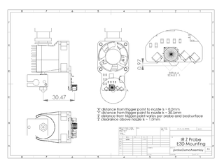
We've designed these boards to couple to a standard 30mm fan - this means they're immediately compatible with all E3D-V6 and Lite6 HotEnds, mounting directly to the fan with no modification or adaptor necessary. Additionally, these boards use a lightweight cable with a compact connector, in order to make wiring as easy as possible.
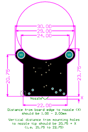
To mount to a printer without a suitable 30mm fan, all that is required are two screw holes. These should be spaced 24mm apart horizontally, and at a distance of 22mm above the tip of the nozzle. See the attached mechanical drawings for further information.
These probes will trigger at a distance of 3mm from the print surface. Recommended mounting height is that the bottom edge of the PCB be 1-2mm above the tip of the nozzle, and the probe's Z-offset can be tweaked in firmware to achieve the desired bed-levelling results.
Specifications
- Dimensions: 30.00x23.75mm
- Weight: 2.5g (excluding cable)
- Trigger distance: 3mm from edge of PCB
- Trigger Repeatability: 0.005mm (5µm) Standard Deviation
- Included Cable Length: 100cm
Improvements from 1.3
Compact Form Factor
- capacitor C1 decreased in height to reduce profile of board, easier to fit probe in tight spaces
- smaller JST-SH connector used, connector no longer protrudes from body of probe
Selectable Digital or Analog Output
- separate output pins for both modes
- mode no longer dependent on automatic detection of control board
Improved Control Board Compatibility
- strong pull-ups on certain control boards no longer prevent probe from working
General Improvements
- faster boot time (<1s instead of 6s)
Backwards Compatibility
V1.4 is largely backwards compatible with V1.3. The mechanical mounting holes and dimensions are identical, and all mounting arrangements for V1.3 should work fine with V1.4.
Notably, the provided cable is different, so a re-wire may be necessary to swap to V1.4.
HotEnd Compatibility
These are the HotEnds we've tested with or had reports of success with. If you're interested in trying something different, or if you've tried a different HotEnd with our probe, let us know how it went!
| HotEnd
|
Compatible
|
Adaptor Required
|
Notes
|
| E3D-V6
|
Yes
|
No
|
Mounts to fan duct with existing screws
|
| E3D-Lite6
|
Yes
|
No
|
Mounts to fan duct with existing screws
|
| E3D Chimera
|
Yes
|
No
|
Mounts to fan duct with existing screws
|
| E3D Cyclops
|
Yes
|
No
|
Mounts to fan duct with existing screws
|
| E3D-V6 or Lite6 with Volcano
|
Yes
|
Yes
|
Printable adaptor available here.
|
| Mark8 Extruder + Hotend Combination
|
Yes
|
Yes
|
Printable adaptor available here.
|
Electronics Compatibility
These are the boards we have tested the probe with. It is likely the probe is compatible with other boards as well - if you try a different control board and it works, let us know so we can add it to the list.
| Motherboard
|
Electronics Compatible
|
Connector Compatible
|
Notes
|
| RAMPS
|
Yes
|
Yes
|
Connect to Z-min endstop, leave 4th pin (yellow) disconnected
|
| RAMBO
|
Yes
|
Yes
|
Connect to Z-min endstop, leave 4th pin (yellow) disconnected
|
| RUMBA
|
Yes
|
Yes
|
Connect to Z-min endstop, leave 4th pin (yellow) disconnected
|
| Smoothieboard
|
Yes
|
Yes
|
Connect to Z-min endstop, leave 4th pin (yellow) disconnected
|
| Melzi
|
Yes
|
No
|
Wires must be cut for screw terminals, and 5V wired to separate pin. Wiring sketch included below
|
| Duet
|
Yes
|
No
|
Need to change order of pins in connector to suit, simple to do though
|
| Azteeg X5 Mini
|
Yes
|
No
|
Wires must be cut for screw terminals
|
| MKS Gen / Base Boards
|
Yes
|
No
|
Some boards need different connector
|
Configuring Firmware
IR Probe Firmware Setup (Marlin 1.1.0-RC1+)
IR Probe Firmware Setup (Marlin 1.1.0-RC4+)
IR Probe Firmware Setup (Smoothieware)
Connecting
RAMPS, RAMBO, RUMBA
Each IR Z Probe comes with a cable that will connect directly to the endstop pins on these control boards. No modification should be required. Make sure to align and orient the connector correctly - the red wire should match the '+' indicator on the board.
Azteeg X5 Mini
Screw terminals are used to connect bare wires to the X5 for all endstops. The included cable will need the connector removed / cut off, and each wire stripped back to allow connection.
Notes
After receiving power the on-board LED will flash twice, indicating the board is ready for use.
Buy It
Store Page
Resources
Links
STL Placeholder / Model of IR Probe V1.4 (Thingiverse)
Printable mount for MaxMicron printers (Thingiverse)
Printable mount for MK8 Extruder + Hotend combo (Thingiverse)
Printable mount for MK8 Extruder + Hotend combo (Thingiverse)
Printable mount for NEMA-17 motors (Thingiverse)
Printable mount for E3D Volcano (GitHub)


