IR Probe 1.4
Overview
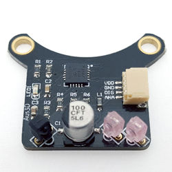
These 3D Printer IR Probes use modulated infra-red light to accurately detect proximity to the print surface, allowing for quick and precise probing of the print surface. Many 3D printer firmwares can use this probing information to automatically level the bed while printing, compensating for some degree of unevenness in the print surface.
These probes are essentially a high-repeatability non-contact proximity sensor. From the perspective of the control board and printer firmware, they can be treated as any other endstop - when connected to power (5V/3.3V & GND) and a signal pin, they will output either a high voltage (indicating the sensor is triggered) or low voltage (sensor is not triggered). Therefore, no special firmware configuration is needed beyond the basics (configuring signal pin and polarity).
Compared to mechanical probe solutions - such as a servo and microswitch - these probes have the advantage of requiring no moving components, weighing less, and having a higher degree of repeatability and reliability. Compared to inductive or capacitive probes, these boards are less dependent on the material of the print surface, working even on glass, and do not require any special electronics or wiring to interface with most printer control boards. Combined with a high degree of immunity from background IR sources, these boards are ideal for nearly any printer build.
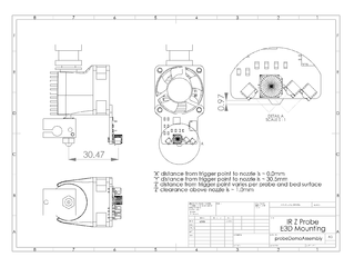
These probes are designed to mount to a 30mm fan - this means they're immediately compatible with all E3D V6 and Lite6 HotEnds, mounting directly to the fan with no modification or adaptor necessary. Additionally, these boards use a lightweight cable with a compact connector, in order to make wiring as easy as possible.
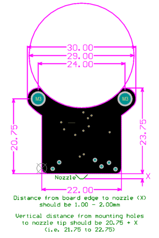
To mount to a printer without a suitable 30mm fan, all that is required are two screw holes. These should be spaced 24mm apart horizontally, and at a distance of 22mm above the tip of the nozzle. See the attached mechanical drawings under Resources for further information.
These probes will trigger at an approximate distance of 3mm from the print surface. Recommended mounting height is that the bottom edge of the PCB be 1-2mm above the tip of the nozzle, and the probe's Z-offset can be tweaked in firmware to achieve the desired results.
Advantages
- Easy to install:
- Mounts directly to E3D V6 & Lite6, printable adaptors available for many other hotends & printers (see HotEnd Compatibility)
- Plugs directly into many common control boards through included cable (see Electronics Compatibility)
- Works with many common bed surfaces
- Lightweight (<3g)
- Compact
- No moving parts
- High repeatability for accurate bed levelling
Specifications
- Input Voltage: 3.3-5V
- Dimensions: 30.00x23.75mm
- Weight: 2.5g (excluding cable)
- Trigger distance: 3mm from edge of PCB
- Trigger Repeatability: 0.005mm (5µm) Standard Deviation
- Included Cable Length: 100cm
Setup
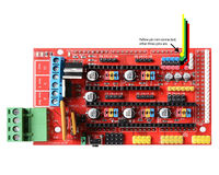
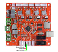
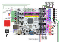
The probe requires three pins be connected to function properly - power (3.3 - 5V, red wire), ground (black wire) and the output signal (green wire). On most control boards these can be connected directly to the endstop pins - see Electronics Compatibility for wiring info on specific control boards.
On some control boards and firmware combinations (mainly Duet and RepRapFirmware), the fourth yellow wire can be used to enable additional probing features. This wire is not required for most control boards or firmwares, and this yellow wire can be left unconnected.
Once connected, when the printer is powered on (or when power is provided to the probe) there is a red LED on the probe that will flash twice to indicate the probe is ready for use. If this LED does not flash when the probe is connected / powered, check all wiring connections and ensure they are correct. This behaviour is independent of the printer's firmware - i.e., as long as the probe receives power this flashing should take place.
Once the probe has started (after the double flash) it will begin acting as a proximity sensor. You can test that the probe is operating correctly by bringing the active edge of the probe (lower edge) near to your bed surface (or other flat surface). When the surface is within the trigger distance, the on-board red LED will turn on. The LED will turn off whenever the probe is not triggered. Again, this behaviour is independent of the printer's firmware and configuration - so you can test the probe is functional before configuring or torubleshooting the firmware.
Changelog
v1.41
- Capacitor C1 changed from SMD to through-hole part, increasing sturdiness
- PCB routing updated to improve manufacturing yield
v1.4
- Overall size reduced
- Capacitor C1 decreased in height to reduce profile of board, easier to fit probe in tight spaces
- Smaller JST-SH connector used, connector no longer protrudes from body of probe
- Selectable Digital or Analog Output
- Separate output pins for both modes
- Mode no longer dependent on automatic detection of control board
- Improved Control Board Compatibility
- Strong pull-ups on certain control boards no longer prevent probe from working
- Faster start-up time (<1s instead of 6s)
Note: v1.4 is largely backwards compatible with v1.3. The mechanical mounting holes and dimensions are identical, and all mounting arrangements for v1.3 should work fine with v1.4. Most significantly, the provided cable is different, so a re-wire may be necessary to swap to v1.4.
HotEnd Compatibility
These are the HotEnds we've tested with or had reports of success with. If you're interested in trying something different, or if you've tried a different HotEnd with our probe, let us know how it went!
| HotEnd | Compatible | Adaptor Required | Notes |
| E3D-V6 | Yes | No | Mounts to fan duct with existing screws |
| E3D-Lite6 | Yes | No | Mounts to fan duct with existing screws |
| E3D Chimera | Yes | No | Mounts to fan duct with existing screws |
| E3D Cyclops | Yes | No | Mounts to fan duct with existing screws |
| E3D-V6 or Lite6 with Volcano | Yes | Yes | Printable adaptor available here. |
| E3D Titan Aero | Yes | Yes | Printable adaptor available here. |
| Mark8 Extruder + Hotend Combination | Yes | Yes | Printable adaptor available here. |
Electronics Compatibility
These are the boards we have tested the probe with. It is likely the probe is compatible with other boards as well - if you try a different control board and it works, let us know so we can add it to the list.
Configuring Firmware
IR Probe Firmware Setup (Marlin 1.1.0+)
IR Probe Firmware Setup (Marlin 1.1.0-RC4+)
IR Probe Firmware Setup (Marlin 1.1.0-RC1+)
IR Probe Firmware Setup (Smoothieware)
Buy It
Resources
Links
STL Placeholder / Model of IR Probe V1.4 (Thingiverse)
Printable mount for MaxMicron printers (Thingiverse)
Printable mount for Geeetech Prusa i3 X (Thingiverse)
Printable mount for MK8 Extruder + Hotend combo (Thingiverse)
Printable mount for MK8 Extruder + Hotend combo (Thingiverse)
Printable mount for NEMA-17 motors (Thingiverse)
