Difference between revisions of "Mark2 Electronics Installation"
(→Power) |
(→Power) |
||
| Line 3: | Line 3: | ||
== Power == | == Power == | ||
{{Caution|The power supply has a switch to select between 110/240V. Please make sure the power supply is set for the appropriate voltage for your region before connecting it to power.}} | {{Caution|The power supply has a switch to select between 110/240V. Please make sure the power supply is set for the appropriate voltage for your region before connecting it to power.}} | ||
It is easiest to wire the power supply to the mains input panel before installing them in place. | |||
=== Wiring === | |||
Requires: | |||
* {{Qty|1|Mains Harness}} | |||
* {{Qty|1|12V Power Supply Unit}} | |||
* {{Qty|1|IEC320 Mains Socket Panel}} | |||
{{Caution|Always take care when dealing with electricity. You should make sure that the printer is disconnected from power whenever doing any wiring.}} | |||
Loosen the screws on the L, N and G terminals of the power supply. Insert the forked end of each length of wire into one of the terminals, and re-tighten the terminal so that the wire is held in place. Attach the other ends of the wires to the mains panel as shown. | |||
=== Power Supply === | === Power Supply === | ||
Requires: | Requires: | ||
| Line 20: | Line 32: | ||
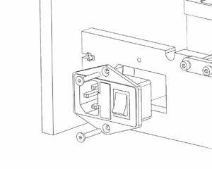
The mains power panel allows the use of a disconnect-able power cable, and makes it easy to quickly switch power on or off if needed. Bolt the panel in place as shown. | The mains power panel allows the use of a disconnect-able power cable, and makes it easy to quickly switch power on or off if needed. Bolt the panel in place as shown. | ||
== RAMPS == | == RAMPS == | ||
Revision as of 10:25, 29 November 2015
Power
| Caution: | The power supply has a switch to select between 110/240V. Please make sure the power supply is set for the appropriate voltage for your region before connecting it to power. |
It is easiest to wire the power supply to the mains input panel before installing them in place.
Wiring
Requires:
- 1x Mains Harness
- 1x 12V Power Supply Unit
- 1x IEC320 Mains Socket Panel
| Caution: | Always take care when dealing with electricity. You should make sure that the printer is disconnected from power whenever doing any wiring. |
Loosen the screws on the L, N and G terminals of the power supply. Insert the forked end of each length of wire into one of the terminals, and re-tighten the terminal so that the wire is held in place. Attach the other ends of the wires to the mains panel as shown.
Power Supply
Requires:
- 1x 12V Power Supply Unit
- 4x M3x15mm Bolt
- 4x M3 Spring Washer
- 4x M3 Plastic Spacer
Attach the power supply to the inside of the printer frame as shown. The bolts will only enter a short way into the power supply, so be sure to use the plastic spacers as shown.
Mains Power Connector
Requires:
- IEC320 Mains Socket Panel
- 2x M3x20mm Countersunk Bolt
- 2x M3 Hex Nut
The mains power panel allows the use of a disconnect-able power cable, and makes it easy to quickly switch power on or off if needed. Bolt the panel in place as shown.
RAMPS
Power Input
Four lengths of wire are included with the electronics - two red and two black. Wire them into the power supply as shown, then secure them in place with a cable tie to be safe. Run the wires along the back of the printer, and up to the RAMPS board. Connect the wires to the power input terminals, noting the polarity as marked on the PCB.
Motor Connections
Thermistors
EndStops
Heating Elements
Fans
In a single-extruder setup, RAMPS has one connection dedicated to controlling a fan. However, we need to run two fans (technically we only need to control the print fan, the HotEnd fan just needs to be on whenever the printer is running). To make this easier, each Mark2 kit comes with a fan expansion board which plugs directly into RAMPS. If you are assembling a single-extruder printer, you will have received a TinyFan board (2 fans). If you are assembling a dual-extruder printer, you will have received a MightyFan board (4 fans). For detailed instructions, refer to the page for each board (linked above).
Here are the important steps for using these boards with the Mark2 printer:
- Screw power wires into fan board terminals
- Attach board to RAMPS
- Screw power wires into RAMPS terminals
- Connect fans in order:
- 1: Print cooling fan
- 2: HotEnd 1 Fan
- 3: HotEnd 2 Fan (Dual-Extruder Only)
- 4: Not Connected (Dual-Extruder Only)
Optional: LCD Add-on
Mount LCD Control Panel
Connect Cables
Optional: Raspberry Pi
The Mark2 frame has mounting holes for a Raspberry Pi model A+, B+, or Pi 2 B, which can be handy if you want to set up an OctoPrint server to control your printer remotely.
Other Electronics
Frame also has mounting points for these RAMPS alternatives:
- Melzi
- Smoothieboard
Other Resources
http://reprap.org/wiki/RAMPS_1.4
http://www.reprap.org/mediawiki/images/0/06/RAMPS_dossier.pdf
http://reprap.org/wiki/Prusa_i3_Rework_Electronics_and_wiring
http://www.nextdayreprap.co.uk/wiring-reprap-prusa-mendel-build-manual/
