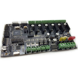
RUMBA Plus
Introduction
RUMBA+ is an updated version of the RUMBA 3D Printer control board, originally developed by RepRapDiscount.
The RUMBA+ update is designed to address several shortcomings with the original design, and improve on the otherwise solid framework it presents. More information on RUMBA is available on the RepRapWiki page here.
In keeping with the original RUMBA design, RUMBA+ is fully open source.
Features / Specifications
- Compact size: 140mm x 75mm
- Fully integrated all in one solution:
- Arduino 2560-R3 compatible (works with Sprinter, Repetier-Firmware, Marlin out of the box)
- ATmega16U2 (with genuine Arduino firmware) for high speed USB serial connection
- Universal power:
- Can be used with 12V-35V for motors / heated bed
- Replaceable automotive-style blade fuses
- Integrated high precision power regulators (DC/DC) for:
- 12V (Fan/Light/...) and
- 5V (ATmega2560/Logic)
- Power input selector for ATmega/logic (stand alone or power from USB)
- Easy display + SD-Card connector:
- RepRapDiscount SmartController compatible pin header on board
- Up to 6 motor driver with easy micro stepping setup (micro switches) which can be used for:
- TRIPLE extruder
- DUAL Z driver and DUAL extruder
- ...
- 5x temperature ADC connectors for thermistors:
- e.g. 3x extruder thermistor + 1x heated bed thermistor + 1x chamber thermistor
- 5x PWM capable power mosfet outputs (3 with voltage selector for MainPower/12V):
- e.g. 3x (MainPower) extruder heater cartridge/power resistor + 1x (12V) fan + 1x (12V) light
- 1x PWM capable power mosfet with extended cooling area for heated bed
- 6x end stop connectors with power supply
- Xmin/Xmax/Ymin/Ymax/Zmin/Zmax
- Can be used for mechanical, opto, hall, ... end stops
- Screw terminals and pin header for easy motor connection:
- Can be used with existing 4 pin plug on motor cable
- Easy to attach cables without plug
- USB connector and USB pin header (useful when mounting in a small box)
- Power and ALL unused pins available on EXP-3 feature connector:
- +5V and +12V
- 2x ADC
- 2x PWM I/O
- 4x I/O
- I2C
- I2C Header Bank
- Support for up to four I2C Encoder Modules
- Full JTAG support
- JTAG can be used during full operation (no shared pins)
- Easy to develop/debug new or optimized firmware using Atmel Studio
Changes from original RUMBA
Input Voltage Compatibility
While the original RUMBA board claims compatibility with power supplies ranging from 12-35V, it uses PTC resettable fuses that are rated for 16V maximum. This means that the board requires modification to be used at voltages above this - though some manufacturers or suppliers may have modified the fuses or shipped boards without them to suit higher voltages.
The RUMBA+ upgrade replaces the PTC fuses with replaceable automotive blade fuses, which are suitable for operating at up to 35V.
Improved MOSFETs
While the MOSFETs used to drive outputs in the original RUMBA design were sufficient and usually up to the tasks required of them, they did not perform as well as is desirable under heavy loads. This is because they are not true logic-level MOSFETs, and do not switch 'fully' on when being driven by the 5V microcontroller - i.e. they operate in the linear region, not reaching saturation mode. This results in inefficient operation and significant self-heating.
The MOSFETs have been replaced with newer MOSFETs that are logic-level compatible, and that will switch on at a much lower voltage. Additionally, these new MOSFETs also have a much lower on-state resistance, and so will be more efficient and generate less heat while in use.
Further, flyback diodes have been added in order to protect the MOSFETs from back-EMF during switching loads with an inductive component (such as PCB heated beds).
LCD Smart Display Wiring
Labelling on expansion ports 1 and 2 has been updated to match the labelling common to most compatible LCD displays, as it was previously reversed from the norm.
Additional I2C Headers
In order to be able to host the new Aus3D Magnetic Encoder modules, four I2C headers have been added to the board. This allows easy connection of up to four encoder modules, and removes the need for an external splitter cable or adaptor board.
First-Time Setup
Stepper Driver Microstepping
Each attached stepper-driver's microstepping mode is set through a DIP-switch on RUMBA+. You'll need to set each switch to the correct position for your stepper-driver and desired microstepping mode.
For A4988 drivers running at 1/16th microstepping, you'll want each switch in the 'on' position.
Install Fuses
Each RUMBA+ board comes with blade-fuses that need to be installed before use. The fuses supplied come in two different ratings - the higher-rated fuse (20A) is for the heated bed, and goes in the fuse-holder nearer the edge of the board. The smaller fuse (10A) goes in the other fuse holder. Your RUMBA+ board should have come with a spare for each fuse.
Wiring
There are good wiring diagrams available on the RepRap Wiki's RUMBA page - the wiring for RUMBA+ is nearly identical, and those images are an excellent starting point.
Troubleshooting
Nothing yet.
Source Files
RUMBA+ is open source hardware - all source files are available on GitHub under the GPL V2 License.
Purchase
RUMBA+ is available for purchase on the Aus3D store, here.

