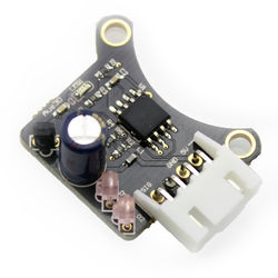
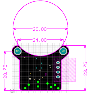
IR Probe 1.3
Overview
Specifications
HotEnd Compatibility
These are the HotEnds we've tested with or had reports of success with. If you're interested in trying something different, or if you've tried a different HotEnd with our probe, let us know how it went!
| HotEnd | Compatible | Adaptor Required | Notes |
| E3D-V6 | Yes | No | Mounts to fan duct with existing screws |
| E3D-Lite6 | Yes | No | Mounts to fan duct with existing screws |
| E3D Chimera | Yes | No | Mounts to fan duct with existing screws |
| E3D Cyclops | Yes | No | Mounts to fan duct with existing screws |
| E3D-V6 or Lite6 with Volcano | Yes | Yes | Printable adaptor available here. |
| Mark8 Extruder + Hotend Combination | Yes | Yes | Printable adaptor available here. |
Electronics Compatibility
These are the boards we have tested the probe with. It is likely the probe is compatible with other boards as well - if you try a different control board and it works, let us know so we can add it to the list.
| Motherboard | Connector Compatible | Electronics Compatible | Notes |
| RAMPS | Yes | Yes | |
| RAMBO | Yes | Yes | |
| RUMBA | Yes | Yes | |
| Melzi | No | Yes | Wires must be cut for screw terminals, and 5V wired to separate pin. Wiring sketch included below. |
| Duet | No | Yes | Need to change order of pins in connector to suit, simple to do though. |
| Smoothieboard | No | No | Pullup too strong, external resistor required between ground and signal (value uncertain, 500R-1.8K, experimentation needed). |
| Azteeg X5 Mini | No | No | Pullup too strong, external 1.6K resistor required between ground and signal. |
| MKS Gen / Base Boards | No | No | Pullup too strong, external 560R resistor required between ground and signal. |
Configuring Marlin
The pullup for the Z_MIN endstop needs to be enabled. Uncomment the line:
#define ENDSTOPPULLUP_ZMIN
The endstop should be set to non-inverting:
const bool Z_MIN_ENDSTOP_INVERTING = false; // set to true to invert the logic of the endstop.
Enable auto-bed levelling:
 #define ENABLE_AUTO_BED_LEVELING // Delete the comment to enable (remove // at the start of the line)
 #define Z_PROBE_REPEATABILITY_TEST  // If not commented out, Z-Probe Repeatability test will be included if Auto Bed Leveling is Enabled.
Recommended bed levelling mode is grid:
#define AUTO_BED_LEVELING_GRID
Adjust the coordinates that define the corners of the probed grid:
 #define LEFT_PROBE_BED_POSITION 50
 #define RIGHT_PROBE_BED_POSITION 150
 #define FRONT_PROBE_BED_POSITION 20
 #define BACK_PROBE_BED_POSITION 180
Set the grid size:
#define AUTO_BED_LEVELING_GRID_POINTS 2
Configure the probe offset from the nozzle. The numbers below are approximately correct for a probe mounted to a forward-facing fan on an E3D V6 or Lite6:
 #define X_PROBE_OFFSET_FROM_EXTRUDER 0     // Probe on: -left  +right
 #define Y_PROBE_OFFSET_FROM_EXTRUDER -25   // Probe on: -front +behind
 #define Z_PROBE_OFFSET_FROM_EXTRUDER -1.5  // -below (always!)
Configure homing / probing settings:
 #define Z_RAISE_BEFORE_HOMING 4       // (in mm) Raise Z before homing (G28) for Probe Clearance.
                                       // Be sure you have this distance over your Z_MAX_POS in case
#define XY_TRAVEL_SPEED 8000 // X and Y axis travel speed between probes, in mm/min
 #define Z_RAISE_BEFORE_PROBING 5   //How much the extruder will be raised before traveling to the first probing point.
 #define Z_RAISE_BETWEEN_PROBINGS 2  //How much the extruder will be raised when traveling from between next probing points
 #define Z_RAISE_AFTER_PROBING 5    //How much the extruder will be raised after the last probing point.
When using a probe instead of an endstop, it's a good idea to enable Z_SAFE_HOMING. This moves the probe to the center of the bed before homing:
#define Z_SAFE_HOMING // This feature is meant to avoid Z homing with probe outside the bed area.
By default the point that the probe homes at should be the center of the bed - however some versions of Marlin contain a bug where the probe point is miscalculated. To be safe, you can manually define the probe point:
 #define Z_SAFE_HOMING_X_POINT (100)    // X point for Z homing when homing all axis (G28)
 #define Z_SAFE_HOMING_Y_POINT (100)    // Y point for Z homing when homing all axis (G28)
Connecting
RAMPS, RAMBO, RUMBA
Each IR Z Probe comes with a cable that will connect directly to the endstop pins on these control boards. No modification should be required.
Azteeg X5 Mini
Screw terminals are used to connect bare wires to the X5 for all endstops. The included cable will need the connector removed / cut off, and each wire stripped back to allow connection. In addition, the pull-up resistors on the X5 are not compatible with the IR Z Probe by default. To correct this, a 1.6K resistor can be placed in the screw terminal, between the signal and ground wires. This should allow correct operation of the probe.
Notes
After receiving power, the probe takes a short while before becoming active. The onboard LED will flash twice, and after this the board is ready for use.


